Odyssey RGB card installation
Guide for Odyssey RGB card installation
The installation of the Odyssey RGB board is simple, requiring only a little skill with a soldering iron. In any case, check the list of materials before starting the installation:
- 1 Odyssey RGB Board
- 1 Harness 8 terminals
- 1 Harness 5 terminals
- 1 DIN 8 pin connectorOther required materials that are not included in the kit:
- Soldering iron
- Good quality solder
- Screwdriver
- Drill and bits
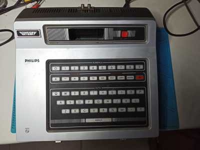
The Odyssey console cabinet is quite large,
but simple to disassemble.
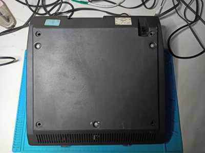
There are only three screws on the bottom,
which can be removed with a screwdriver.
Then just remove that plastic cover.
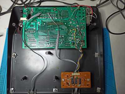
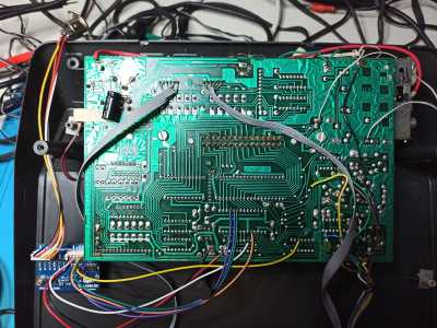
Virtually all Odysseys sold around here are exactly the same,
having their main board (in green) and a small transcoding board on the bottom.
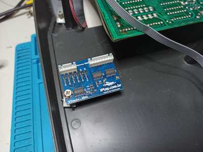
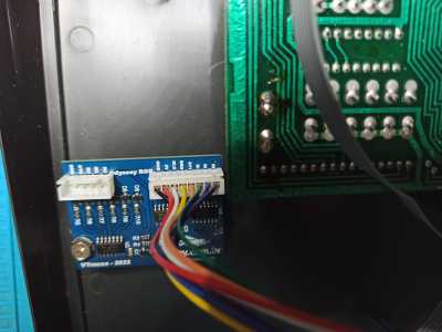
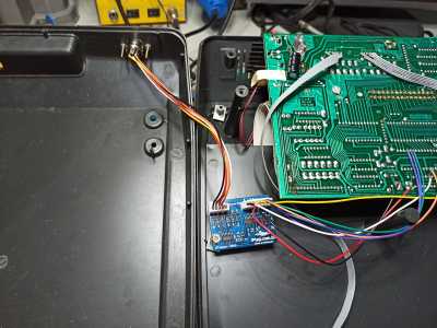
We can attach our little board to the plastic "post" on the left side.
I used a computer cabinet screw, since it doesn´t require a great deal of tightening,
just enough for the board to stay in position.

Make the 8-pin harness connection, noting the correct side.
Also check the colors of your cable, because they may be different from the picture.
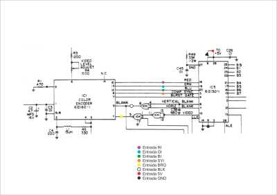
This is the wiring diagram we will make,
with each color corresponding to one of the wires in the 8-pin harness.
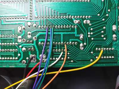
The connections are all made on the main board from the bottom ,
so it does not need to be removed from the cabinet.
Just add some "new" solder to each pin and solder the wire in place.
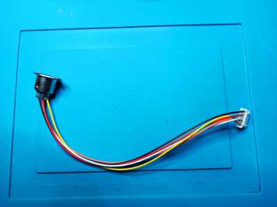
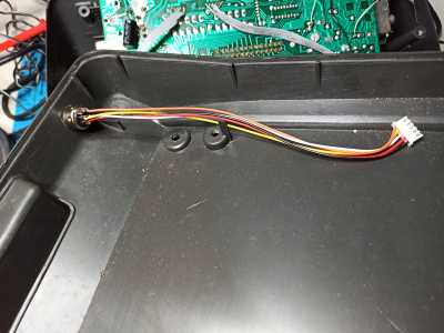
The 5-way harness should be soldered to the DIN connector following the pinning of your preference.
A good example would be to follow the pinning of an MSX RGB, ZX Spectrum or others, and use the same cable you already have at home.
We can even use a SCART connector directly
With all the wires soldered and both harnesses connected to the board,
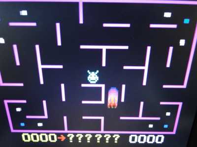
we can do a quick test with the video game even open and turned upside down.
All that is needed is to have a cartridge attached.

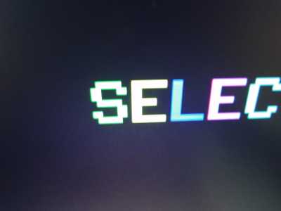
If everything is connected correctly, we will see a clean and perfect image on the monitor or TV.
Just remember that the monitor needs to support 15KHz, example the LG1721/1921 and Samsung 510N or even an upscaler card like GBS8220 and many others.
Once everything is tested and working, let´s move on to completing the installation
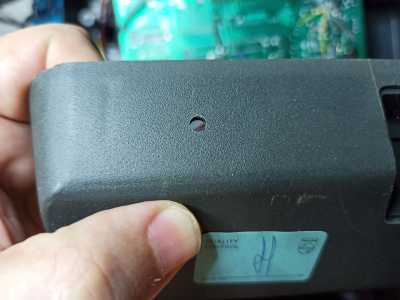
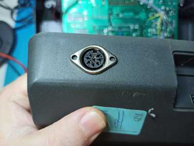
In the bottom piece that closes the Odyssey, the ideal is to drill a guide hole with a small drill bit and then enlarge the hole until it reaches the correct size of the connector.
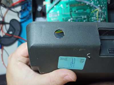
Then it was just fitting the connector in place and drilling the two small "ear" holes.
In the end the cable is attached to the bottom cover of the console,
but it can easily be removed from the RGB board in an eventual maintenance.
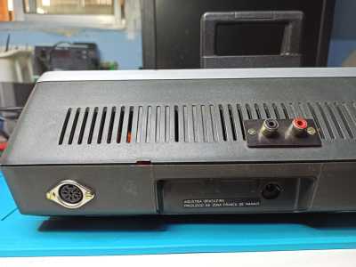
Note that you can even have RGB output and A/V output on the same console.
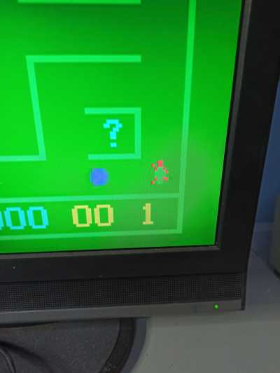
Time to test the final result, which should be a clear, perfect image.

Link to the original article here